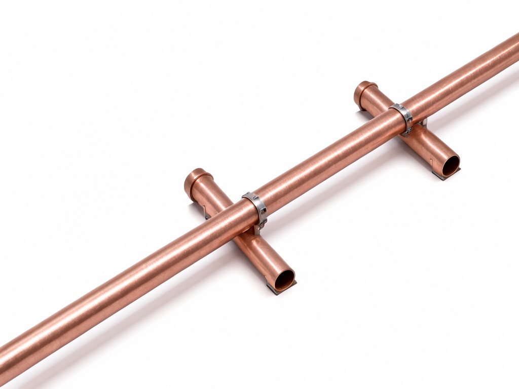
Specifying China copper pipe support spacing for Wholesale and OEM Orders
Support spacing is a system decision, not a universal clamp dimension. Pipe diameter, wall thickness, temper, orientation, temperature change and service load all affect the allowable distance between supports. Select the support body and contact liner for the pipe first; confirm spacing against the project design and applicable local requirements.
Material choice starts with the conditions the copper tube will meet. Importers qualifying a second source need more than a matching nominal size: a clamp that leaves a hard edge against the tube can mark or wear it, while an undersized body can pinch the pipe as installers tighten it. Our supply scope centres on formed support hardware and compatible liners for copper pipe runs, with product dimensions and spacing guidance kept distinct from the engineer’s final installation schedule.
Scope of Supply and Physical Form
For wholesalers and private-label buyers, the order can cover pipe clamps, saddle supports, brackets and separating inserts sized to the nominated copper tube outside diameter. Support spacing is then established for the installed run; it is not an inherent property of the clamp. Horizontal and vertical sections can require different support layouts, and concentrated loads, valves, joints or changes in direction may need local support beyond the regular run spacing.
A second-source comparison should check the usable clamp range, closure geometry, fastener access and liner coverage. Matching only the catalogue size can leave a gap at the contact surface or force the installer to over-tighten the assembly.
How It Is Built and What That Changes
Construction options diverge as soon as weight matters. A stamped and formed metal clamp suits repeat orders with stable dimensions and efficient packing; a heavier bracket or channel assembly may be preferable where the support must connect to a particular structure or accommodate greater load. The forming sequence sets the clamp profile and closure alignment, so tooling control matters most at the tube-contact radius and fastener holes.
Where the tube must be isolated from the support body, a polymer liner separates the two surfaces and can reduce rubbing noise and local wear. The liner also changes fit: a thicker insert reduces the available internal diameter, while a harder compound may transmit more vibration. Finish selection affects corrosion exposure and cost; specify the installation environment rather than choosing a coating by appearance alone.
Formed Clamp with Liner
A practical choice for repeat sizes and routine indoor runs. Confirm liner material, thickness and retention so the insert stays seated during installation.
Heavier Bracket Assembly
A suitable route where mounting geometry or support load drives the specification. More material and a larger package can raise unit and freight cost, so reserve it for defined site conditions.
Where This Product Beats Standard Alternatives
A correctly sized, lined support can prevent the repeat complaints buyers see after installation: copper tube movement, contact noise, surface scoring and visible sag between supports. Those outcomes depend on both support spacing and interface fit. A clamp cannot compensate for a span that exceeds the project design, and a close support layout cannot correct a sharp or uneven contact edge.
Compared with a generic bare-metal clip, a copper-compatible lined assembly adds material and assembly cost but gives the installer a defined separation layer. For basic dry indoor service where the design permits direct support contact, the lower-cost option may be adequate. Where vibration, moisture or thermal movement is expected, the liner and finish should be reviewed alongside the support interval rather than treated as optional upgrades.
What Can Be Customised and What Cannot
Buyer-defined options include fit range, clamp profile, liner selection, finish, fastener configuration, carton quantity and private-label packaging. A sample or approved drawing should lock the tube-contact geometry before production tooling is released. The table below separates factory-controlled choices from installation variables that need project confirmation.
| Item | Order specification | Boundary to confirm |
|---|---|---|
| Pipe fit | Tube outside diameter, clamp opening and liner thickness | Confirm actual tube size and tolerance; nominal trade size alone may not define fit. |
| Body and finish | Metal grade, formed profile and specified surface finish | Corrosion exposure and mounting loads determine suitability; confirm with the project engineer. |
| Liner and pack | Liner compound, colour, retention, label and carton count | Service temperature and contact conditions govern liner suitability; spacing remains a system-design decision. |
OEM and ODM Programme Structure
For a second-source programme, start with the incumbent sample, controlled drawing or a complete fit description. The review should record tube outside diameter, clamp dimensions, liner material, mounting method, finish and packaging. If the drawing leaves the support interval open, keep that as a project-side item rather than turning it into an unverified product claim.
OEM orders can use buyer artwork, carton marks and agreed part references. ODM work can adjust the formed profile or liner interface, subject to tooling review and sample approval. A changed liner or metal thickness can affect fit and closing force, so approve the complete assembly—not a component in isolation—before the production order.
How Consistency Is Held Across Batches
Batch variation most often becomes visible as inconsistent clamp closure, a liner that sits proud, or a finish that differs from the approved sample. These issues can slow installers and trigger returns even when the nominal size appears correct. Production control therefore centres on the approved drawing, tooling condition, incoming material identification and checks on assembled fit.
For repeat orders, retain the signed sample and revision-controlled dimensions as the comparison point. Record any approved substitution before production; a visually similar coating or insert compound may behave differently in the specified environment. Batch labels and carton identification can link incoming inspection findings to the production lot.
Inspection Items and Test Methods
Inspection should match the failure risk and the approved drawing. Dimensional checks cover the opening, formed radius, mounting holes and overall profile; a fit check on a representative tube confirms that the clamp closes without forcing the liner out of position. Visual review can catch burrs, coating skips, edge damage and packing marks before cartons are sealed.
Where the order includes a liner, verify its specified material, dimensions and seating. Fastener engagement and closure can be checked with the agreed assembly method. These factory inspections assess the support component; they do not establish allowable pipe spacing, which must account for the complete run, service conditions and project requirements.
Questions Buyers Ask Before Ordering
Can the factory set a universal spacing for each clamp size?
No. The allowable interval depends on tube dimensions and temper, installed orientation, fluid and temperature conditions, loads, and applicable project requirements. We can provide product dimensions and review the buyer’s application data, but the installation spacing needs design approval for the specific system.
What information is needed to match an existing support?
Send the tube outside diameter, a dimensioned drawing or sample, mounting details, liner requirements, finish and intended service environment. Photos help identify geometry, but they do not replace measurements for tooling approval.
Can a new liner be introduced without changing the clamp?
Sometimes, but liner thickness and hardness change the internal fit and closing feel. Test the proposed liner inside the actual clamp with the nominated tube before approval. If it changes the assembled dimensions, the clamp profile may also need revision.
How can we qualify a second source without committing to production tooling immediately?
Begin with a sample review against the incumbent dimensions and intended pipe fit. Confirm what can be made from existing tooling and which profile changes require new tooling, then approve the assembled sample and packaging details before placing a volume order.
Request a Sample for Fit Review
Share the tube size, support drawing or incumbent sample details, liner preference and target order configuration. We can review the fit, identify any tooling change and prepare a sample for your second-source qualification.
Contact us to request a sample and include the project conditions relevant to support spacing.